Home » Centrifugal fluid handling pumps » Magnetic drive centrifugal pumps series COMPASS » CM30 – Magnetic Drive Centrifugal Pumps
COMPASS
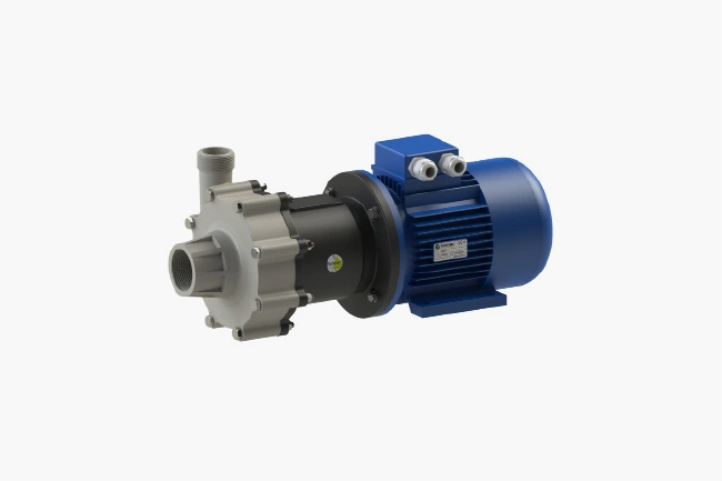
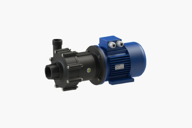
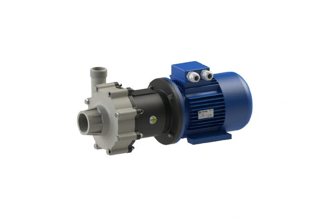
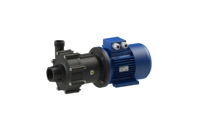
CM30 - Magnetic Drive Centrifugal Pumps


Performance
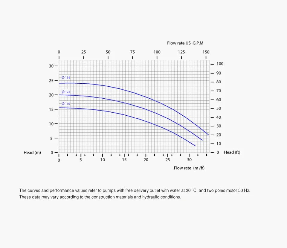
PERFORMANCE CURVES
To determine the correct size of a centrifugal pump it is of fundamental importance to know the actual working point of the system, therefore the flow rate (Q) [m3/h] and the head (H) [m.c.l. or m] required, to identify the pump performance curve on which the point is available. Normally the graph of the pump performance curve indicates on the x-axis the flow rate, therefore the quantity of fluid that can be moved in a given time interval, and on the y-axis the head, i.e. the available energy that can be transferred to the fluid. As the flow rate increases, the available head decreases.
The absorbed power curve (P) [kW] represents, on the ordinate axis, the electrical power used characterized in relation to the required flow rate Q. The specific weight of the liquid must be multiplied by the power absorbed by the pump itself in order to define the necessary power and therefore the correct motor to install. It is recommended to add 10-20% as a safety margin to the value obtained.
The efficiency (η) is the relationship between the power supplied and the power actually used and depends on the required operating point. It is important to ensure that the selected pump, at the required flow rate, is operating in the area of maximum efficiency (maximum efficiency point – BEP, Best Efficiency Point), thus avoiding a selection at the beginning or end of the curve.
Ask for advice
Do you need support in choosing the centrifugal pump most in line with your specific fluid handling needs?
Fill out the form below and you will be contacted by our staff.
The best solutions, certified


