Magnetic Drive Centrifugal Pumps
Compass
The COMPASS series magnetic drive centrifugal pumps are made of polypropylene and PVDF and are suitable for highly corrosive liquids.
Thanks to the innovative magnetic drive system, the COMPASS series reduces the risks of leaks, emissions, and maintenance costs.
Motion is transmitted through magnetic couplings without any mechanical seal, and this design ensures maximum safety and efficiency.
The pumped liquid must be clean and free of suspended solids.
OPERATING PRINCIPLE OF THE CENTRIFUGAL PUMP
The centrifugal pump is a hydraulic pump (turbomachine) that processes the working fluid in a constant volume over time through always open channels, with typically stationary flow (thus, no valves are needed inside).
When the impeller is rotated, it also imparts rotation to the fluid (kinetic energy) and a depression in the suction duct which, along with the thrust of atmospheric pressure, sucks the liquid into the centrifugal pump.
The fluid follows a trajectory from the center of the impeller to its periphery due to the action of centrifugal forces, and passes through the increasingly large channels formed by the curved blades. Already in this path, part of the kinetic energy is transformed into pressure energy.
Upon exiting the impeller, the fluid enters the volute, which also has an increasing section, and the remaining amount of kinetic energy is transformed into pressure energy, increasing the head. The more pressure energy transferred to the fluid, and therefore the head of the pump, the further the working fluid can be sent.
The operating range of the centrifugal pump is strictly limited to its characteristic curve.
FEATURES OF THE CENTRIFUGAL PUMP
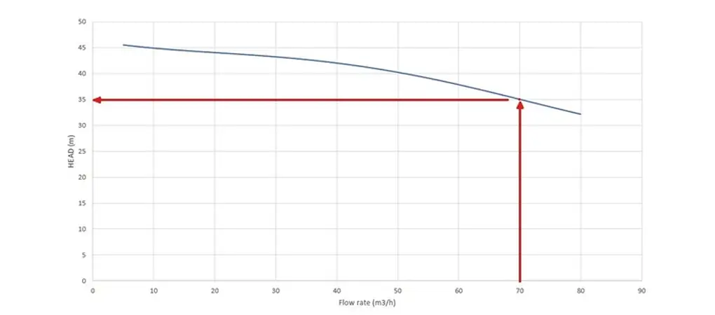
Each centrifugal pump has its own characteristic curve, which is the graphical representation of the pump’s performance.
- On the x-axis (horizontal axis) is reported the flow rate Q, usually in m3/h. It indicates the amount of fluid that passes through each section of the centrifugal pump over a defined period. This quantity depends on the dimensional characteristics of the pump, the number of motor revolutions (i.e., the speed of rotation of the impeller), and the characteristics of the fluid (density and viscosity depending on the temperature). The flow rate affects all the performances of the centrifugal pump and is the first technical parameter to consider.
- On the y-axis (vertical axis) is instead reported the head H, usually in meters. It is calculated from the pressure difference between the outlet and the inlet of the centrifugal pump and represents how far the fluid can be pushed if it encounters resistance along its path, such as height, curves, or valves.
Let’s define:
ΔZ the height difference between the lower basin A and the upper basin B;
PA and PB are the pressures acting respectively on the free surface of the upper basin A and the free surface of the upper basin B;
γ = specific weight of the fluid (= fluid density*gravity acceleration g);
- ΣY the sum of distributed and localized losses within the system.
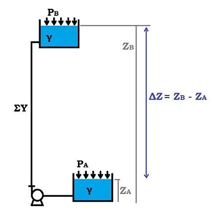
In ideal conditions, with perfectly smooth conduits, without curves, valves or filters, thus
ΣY = 0 and with PA = PB = ambient pressure, we would have that H = ΔZ, so the centrifugal pump provides all the energy to overcome only the height.
In reality, the pump must overcome more than just the height difference as ideal conditions can never be reached, so the head that must be achieved is
H = ΔZ + (PB – PA)γ + Σ Y
Once the dimensions of the centrifugal pump (impeller and volute) and the speed of rotation of the impeller (given by the motor’s RPM) are established, the characteristic curve is unique and typical for each pump.
Knowing the specific weight of the fluid γ, it’s also possible to calculate the theoretical power W, in Watts, required to move it:
𝑊 = 𝛾 ⋅ 𝑄 ⋅ 𝐻
For magnetically driven centrifugal pumps, the magnetic torque needed to move the fluid must also be considered.
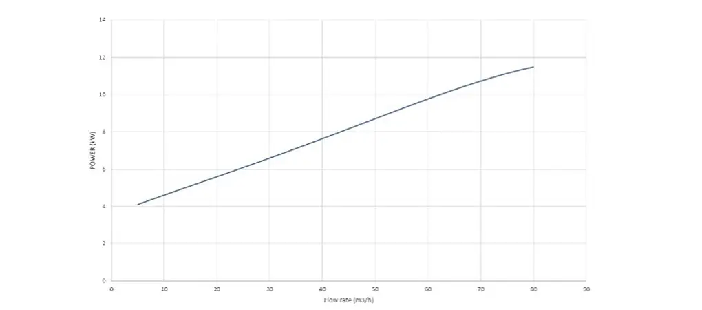
The actual power Wa absorbed by the motor is slightly greater as we must account for friction and fluid dynamic losses within the pump itself, which are considered in the efficiency η. The power curve, always in relation to the flow rate Q, therefore refers to the following formula
𝑊𝑎 = 𝑊/𝜂
It is intuitive to understand that as the flow rate increases, the required power will also increase, as shown in the graph below.
CHOOSING A MAGNETIC DRIVE CENTRIFUGAL PUMP?
The magnetic drive centrifugal pump is suitable for pumping highly corrosive liquids quickly and continuously. However, before choosing this type of pump, it is essential to assess all operating conditions:
- Processed fluid: a magnetic drive centrifugal pump is a high-performance but rather delicate machine. It is therefore necessary for the working fluid to have a low viscosity, up to a maximum of 200 cps (for the largest size). Higher viscosities would require magnetic forces and therefore much higher power, with the risk that the fluid would not be moved at all. It is also important to consider a maximum specific weight of 1.8 kg/L. Higher values would excessively fatigue the impeller and compromise the operation of the motor due to out-of-range absorption.
The closed impeller does not allow the passage of dirty liquids with suspended solids or sludge that would clog it, while metal powders are not compatible with magnets. - Temperature: Fluimac magnetic drive centrifugal pumps can be used in a range between -5°C and +65°C if made of polypropylene, or in a range between -20°C and +95°C if the centrifugal pump is made of PVDF. It is important that the fluid always remains in a liquid state and that the viscosity does not exceed 200 cps (especially at low temperatures).
- Working conditions: each centrifugal pump has a specific characteristic curve that shows the head [m] that the machine can reach given a certain flow rate [m³/h]. Knowing the conditions of your system before choosing a centrifugal pump prevents the risk of inadequate performance and damage to the system and the machine.
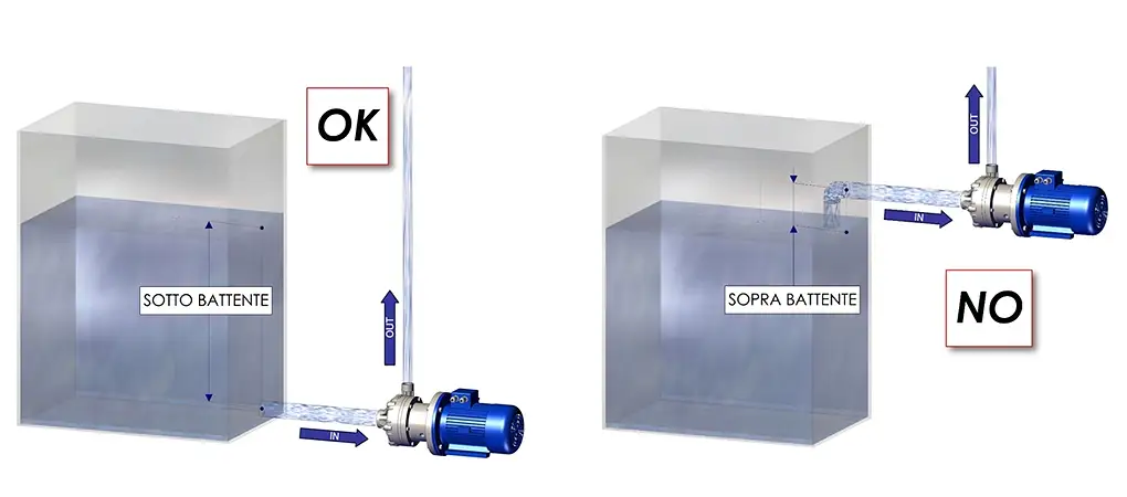
- Configuration: these pumps are not self-priming, so they must be placed outside the withdrawal tank, below the free surface of the fluid, with their axis parallel to the ground.
Advantages of the centrifugal pump
- Safety and efficiency: the impeller and liquid passage chamber are completely separate from the motor and isolated from the external environment by a glass cover that prevents leaks, spills, and emissions. This makes it possible to handle potentially hazardous, toxic, or corrosive liquids in compliance with strict safety and environmental regulations.
- Reduced maintenance costs: magnetic drive pumps have no friction-generating components, so they are less prone to wear and tear and require fewer parts replacements than conventional mechanical seal pumps.
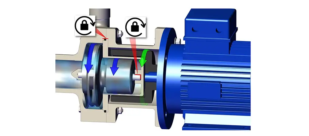
- Easy motor-pump coupling: the absence of a component that transmits motion mechanically facilitates motor-pump assembly. The impeller will align itself with the axis of rotation thanks to the magnetic interaction between the internal magnet and the external magnet.
HOW OUR COMPASS MAGNETIC DRIVE CENTRIFUGAL PUMP IS MADE
The centrifugal pump is a hydraulic operating turbomachine capable of processing the fluid through centrifugal effect in fixed and rotating channels always open, without altering the fluid’s compressibility. Hence the name centrifugal pump. The rotation imparted by the magnets to the impeller provides kinetic energy to the flow (radial acceleration), which is converted into pressure energy in the subsequent diverging channels.
The main components of a magnetic drive centrifugal pump are:
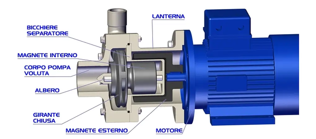
The impeller is the main component of the centrifugal pump and the moving part with which the fluid exchanges energy. Made of plastic material reinforced with fibers (PP + FRP or PVDF + CF depending on the centrifugal pump’s use and the processed fluid), it consists of a series of curved blades forming increasingly larger channels as the radius increases. The closed impeller increases the efficiency of the pump (less head loss) but does not allow the passage of dirty liquids. It is directly keyed to the internal magnet with which it rotates integrally and is supported by a fixed shaft. There is no direct connection between motor and impeller; the motion is transmitted only through magnetic interaction, hence the importance of using low viscosity fluids (max 200 cps).
Different volumetric flows [m³/h] and head [m] can be achieved by controlling the impeller’s diameter, curvature, height, and number of blades.
For each impeller, there will be a characteristic curve of the magnetic drive centrifugal pump, i.e., the head that can be achieved given a certain flow rate, the operating range, and the working point.
- The pump body or volute, snail-shaped, with an increasing section in the direction of motion, allows the fluid to be sucked in axially and discharged radially upwards. In addition to directing the flow, it is also fundamental for the performance of the magnetic drive centrifugal pump: the increasing area appropriately slows down the fluid, so the kinetic energy is transformed into pressure energy.
- The external magnet is keyed to the motor and transmits its rotation to the impeller. It never comes into contact with the fluid, so it is not subject to wear and corrosion phenomena.
- The separator cup ensures the isolation of the fluid and the hydraulic part from the external environment. It is completely sealed to prevent liquid leakage. It divides the impeller (and the internal magnet) from the external magnet and is made of the same material as the pump body to ensure chemical compatibility with the liquid but does not affect magnetic drive. In a magnetic drive pump, the impeller’s concentricity is maintained by magnetic forces in the radial direction and by the fixed shaft relative to the cup.
- The motor is the part that imparts rotation. In most common cases, it is a 2-pole electric motor (about 3000 rpm). Different characteristic curves of the magnetic drive centrifugal pump can be obtained based on the number of revolutions.
How to Use the Magnetic Drive Centrifugal Pump Compass
- Magnetic drive centrifugal pumps operate through the magnetic interaction between an external magnet and an internal magnet attached to the impeller. These forces generate high temperatures, and it is therefore necessary to cool the components.
We have designed them so that this task is always performed by the working fluid, without the use of additional means, but it is important to remember that the magnetic drive centrifugal pump must only be started when filled, never dry, to avoid melting of parts and consequent loss of liquid.
- Magnetic drive centrifugal pumps are an optimal solution when handling highly corrosive, toxic, polluting, or expensive liquids. It’s important that the liquid is clean without suspended solids, which would otherwise obstruct the closed impeller.
- With the magnetic drive pump, it is possible to handle fluids with viscosities up to 200 CPS (with the larger size) or specific gravity up to 1.8 kg/L by increasing motor power. With the same number of rotations per minute [rpm], increasing motor power does not affect the flow rate and head of the centrifugal pump but compensates for the increased effort due to denser liquids. For higher viscosity values, stronger magnetic forces would be required, exceeding the limit compromises the rotation of the impeller and thus the fluid transport;
- A magnetic drive centrifugal pump is a very efficient but delicate machine. It is necessary to know the characteristics of the system and the working fluid to choose the right machine.
- Due to their operating principle, centrifugal pumps create a suction depression. If the absolute pressure at the impeller inlet is lower than the vapor pressure of the working liquid, cavitation occurs (creation of evaporated liquid bubbles and implosion on the impeller). Fluimac magnetic drive centrifugal pumps should be positioned outside the fluid tanks and always installed under head so that the liquid does not have difficulty entering the pump’s suction. However, the maximum suction height can be controlled through NPSH curves: The pump’s NPSH (available) must always be greater than the NPSH required by the system, considering the geodetic height (difference in height between the downstream tank and the pump inlet), the head losses between these two sections, and the pressure difference between the free surface pressure of the downstream tank and the vapor pressure of the liquid.
- In addition to suction conditions, it is essential to know the characteristics of the discharge pipes because they influence the calculation of the head. Before choosing a magnetic drive centrifugal pump, it is necessary to know the head required by the system: to the geodetic height (difference in height between the downstream and upstream tanks through which the fluid is to be moved) must be added all the head losses due to the system. We can divide the losses into two types: distributed and localized. The former depends on the flow of the fluid in the pipes, and it is necessary to know the dimensions and conditions of the pipes, the latter depends on localized factors in the system such as curves, valves, or filters.
- Finally, it is necessary to know the working fluid. Viscosity and density also affect the calculation of head losses and also in the choice of motor power. It is important to remember that viscosity is strongly dependent on the operating temperature. Low temperatures significantly increase viscosity.
Ask for advice
Do you need support in choosing the centrifugal pump most in line with your specific fluid handling needs?
Fill out the form below and you will be contacted by our staff.
The best solutions, certified